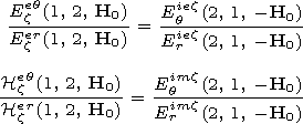
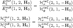
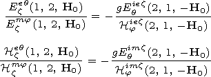
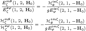
H0) are the
x components of
the fields excited at point 1 under the geomagnetic field
- H0 by the electric or magnetic dipoles directed along
ez and located in the ionosphere at point 2 ( x and
z take the values
r,
q, and
j ). Using
expressions (12), we rewrite the ratios of the ionospheric field
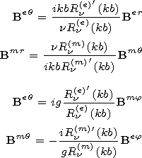
components (14)-(17) in the following form:
 | (18) |
where
Bqx ( q=e, m; x=r, q, j) are six-element column matrices of electric and magnetic
field components.
[12] If the emitter is located on the surface of the ground
(b=a), it
follows from expressions (9) and (18) that
 | (19) |
It is worth noting that in the case of a waveguide irregular on
q, the value
d in expressions (19) should be
considered as the relative surface impedance of the ground in the
regular part of the waveguide where the transmitter is located.
[13] Now we discuss the relationship between the components of the
fields excited in the ionosphere by an emitter of any type located
in the waveguide cavity. Methods and algorithms of field
calculation in the waveguide cavity and in the ionosphere were
developed in detail
[Rybachek, 1995;
Rybachek et al., 1997a, 1997b],
so we do not discuss these methods. As it has been
already mentioned, determination of the fields in the ionosphere
is reduced to an integration of the system of differential
equations for the tangential components of the fields coinciding
by the form with the equations describing propagation of plane
waves in plane-stratified media. The difference is that the
ionospheric properties and the complex angle of wave incidence on
the ionosphere
a(n, r) depend on the radial coordinate.
The
a(n, r) angle is determined by the relation
sin a (n, r)=n/(kr). The radial components of the fields are
found from the Maxwell's equations for the ionospheric plasma. The
asymptotic separation of variables in these equations leads to the
field dependence on the coordinate
q of the type (8)
[see, e.g., Makarov et al., 1994],
so the radial field components
of each of normal waves are described by the following
expressions:
 | (20) |
 | (21) |
Here
exz ( x,
z=r,
q,
j ) are the elements of the relative dielectric
permittivity tensor of the ionosphere and
r is the radial
coordinate of the observation point.
[14] At low altitudes where the ionospheric properties are close to the
properties of the free space, it follows from (20) that the
components of the fields
Er and
Hj are related
by a simple formula
krEr  -n
Hj. In the
general case, the simple relation determined by formula (21)
exists only between the components
Hr and
Ej.
Between the other components, there exists a complicated relation
due, in particular, to a sphericity of the waveguide,
inhomogeneity of the ionosphere, and its anisotropy. However, one
can expect that at large distances from any emitter located near
the ground surface, the fields in the ionosphere would be close to
the fields of plane waves propagating in a magnetoactive
plane-stratified medium. In this case the relation between the
field components are considerably simplified.
[15] Actually, in the region of the ionosphere where the
quasi-longitudinal approximation
 | (22) |
is valid the relations between the field components of a plane
wave have the following form
[Budden, 1961]:
 | (23) |
 | (24) |
 | (25) |
The designations accepted in the magneto-ionic theory are used in
formulae (22)-(25):
 | (26) |
In (25) and (26):
e,
me are the charge and the mass of an
electron, respectively,
N is the electron concentration,
ne is the effective collision frequency of electron with neutral
particles and ions,
n is the refractive index of the ionosphere,
and
Y L and
Y T are the longitudinal and transverse components
of the
Y vector. In the case of a regular waveguide
N and
ne depend only on the radial coordinate. For an irregular
waveguide these parameters depend in addition on the angular
coordinate
q. Expressions (23)-(25) are written in the
spherical coordinates with the aim to use them for the problems
being studied.
[16] Relations (24) and (25) complicated enough because of the complex
parameter
U, are simplified if besides (22) the following
inequalities are fulfilled:
 | (27) |
In this case we have
 | (28) |
 | (29) |
It is worth noting that as it follows from formulae (26) and (29)
for
n2, the values of the refractive indices may be either real
or imaginary. Because of this, out of two propagating upward
characteristic waves only one wave with the real
n is of a
significantly propagating character.
[17] It follows from expression (28) with an allowance for (26) that
 | (30) |
where
H0 L and
H0 T are the longitudinal (radial) and
transverse components of the geomagnetic field, respectively.
[18] Taking into account the relation which follows from (21) and (23)
and expression (29), we find
 | (31) |
Here
|n| is computed from (26) and (29) as
 | (32) |
where
c is the free space velocity of electromagnetic waves.

Powered by TeXWeb (Win32, v.2.0).


 1,
|n|(p-q)
 1 [Erdelyi, 1953]
for each normal wave is described by the following functions
[Makarov et al., 1994;
Rybachek et al., 1997a]:


 1, we
find the ratios of the field components in the waveguide cavity


 d) can be obtained using
expressions (1):


 -n
Hj. In the
general case, the simple relation determined by formula (21)
exists only between the components
Hr and
Ej.
Between the other components, there exists a complicated relation
due, in particular, to a sphericity of the waveguide,
inhomogeneity of the ionosphere, and its anisotropy. However, one
can expect that at large distances from any emitter located near
the ground surface, the fields in the ionosphere would be close to
the fields of plane waves propagating in a magnetoactive
plane-stratified medium. In this case the relation between the
field components are considerably simplified.


