5. Resonant Frequencies
[26] Now we study some features of the character of the dependence of the
functions of influence
KI (12) and
KV (13) on the changing shape and
relative thickness of two layers of the plasma coating. It is worth noting
that because of the dispersion properties of the plasma one can find a
frequency at which the values of
|KI| and
|KV| reach the maximum
(resonance) value. At small losses to emission
(G 1) and small
thermal losses in the plasma (Im
e | Ree|) when
Ree
1) and small
thermal losses in the plasma (Im
e | Ree|) when
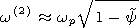
Ree 1- wp2/w2 such resonant frequency in current is determined from
the condition of becoming zero of the real part of the denominator (12)
1- wp2/w2 such resonant frequency in current is determined from
the condition of becoming zero of the real part of the denominator (12)
 | (15) |
or the real part of the denominator (13) for the resonance in voltage
 | (16) |
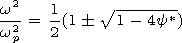
Equations (15) and (16) are biquadratic relative to the resonant
frequency. The roots of the each equation form two branches at a
change of the spheroid shape
Y from strongly prolate to strongly
oblate.
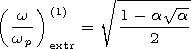
[27] The roots of equation (15) (at
a>0 ) have the form
 | (17) |
and form two branches depending on the spheroid shape
b/a at its fixed
filling in by the vacuum
a.
[28] At continuous changes in the spheroid shape from strongly prolate one
( Y 1,
Y* 0 )
to strongly oblate one 
|
|
Figure 3
|
the
resonant frequency (17) varies from the exit point (the resonance
frequency at
b/a = 0 for the prolate spheroid) to the coinciding to it
entrance point (the resonance frequency at
b/a = 0 for the strongly
oblate spheroid) equal to
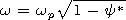
w(1) 0 and
w(2) wp for the low-frequency and
high-frequency branches, respectively. It is worth noting
that for a small filling in of the plasma spheroid by vacuum
( a3 1 ),
the approximate expressions for resonant frequencies (17) for the
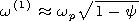
low-frequency
( w(1) )
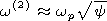
and high-frequency branches
( w(2) )
for the prolate
spheroid
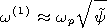
and
and for the oblate spheroid
and
do not describe their values for the oblate shape of the spheroid in the
vicinity of
Y=1/2 ( a 2b ),
where the resonant frequencies (17) have
an extreme
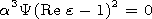
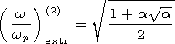 | (18) |
These values (18) tend to the entrance (or exit) points of its branches with an
increase in the filling in
a of the spheroid by vacuum, that is, the curves
of the dependence (17) on the spheroid shape
b/a become less steep.
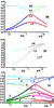
In more detail for the fixed
a, the position of resonance frequencies
(17) as a function of
b/a for the prolate spheroid and of the inverse
parameter
a/b for the oblate spheroid is shown in Figure 3a. Solid and
dashed curves show the low-frequency and high-frequency branches,
respectively, for two values of the relative thickness of the plasma
coating:
a=0.2 and 0.8. The calculation result illustrate the shift of
the resonance frequency to the limiting values
w(1)=0 and
w(2)=wp as the vacuum cavity becomes larger in volume ( a =0.8 ). For the small
vacuum filling in ( a =0.2 ) resonance frequencies (17) have a
well-pronounced extreme for the oblate shape of the spheroid.
[29] In the case of the slot antenna, the roots of equation (16) for the
resonant frequencies have a form of complicated radicals, so their simple
analytical dependence on the problem parameters may be obtained only
in two particular cases:
F=1 and
F=0.
[30] For
F 1 we have a two-layer plasma coating of a weakly prolate
spheroidal shape with a relatively thick first layer
( a03 1, a03 Y ),
and equation (16) coincide with resonant equation (15),
the roots of which are presented by expression (17). Thus, in this case,
the frequencies for the resonances in voltage and current coincide. These
resonant frequencies are shown in Figure 3a.
[31] At the absence of the depleted ion layer ( F=0, a0=1 ), equation
(16) is a resonance one for the spheroidal slot antenna with one-layer
plasma coating
e
. The roots of (16) have one frequency branch
to which (as we will see below) the resonant frequencies of the
high-frequency branch (16) tend with a decrease of the thickness of the first
layer ( a0  1 ).
These frequencies are shown in Figure 3b for two
values of the relative thickness of the plasma coating:
a=0.2 and 0.8.
1 ).
These frequencies are shown in Figure 3b for two
values of the relative thickness of the plasma coating:
a=0.2 and 0.8.
[32] For the
a0 values different from zero and unity, the regularities in the
behavior of the resonant frequency (18) (related to
wp ) are shown in
Figure 3c as a function of the spheroid shape by solid and dashed
curves for the low-frequency and high-frequency branches, respectively,
for three values of the relative thickness of the first layer
a0.
Curves 1
and 2 correspond to
a0 = 0.2,
a=0.2 and 0.8;
curves 3 and 4
correspond to
a0 =0.8,
a=0.2 and 0.8; and curves 5 and 6
correspond to
a0 =0.99,
a=0.2 and 0.8.
[33] For the relatively thick first layer
( F 1,
a03 1 )
the dependence of
the resonant frequencies in voltage (curves in Figure 3c) coincide with
the corresponding dependence for the resonance in current
(curves that correspond to
a= 0.2 and 0.8 in Figure 3a).
[34] In the case when the thickness of the first layer becomes too small
( F 0,
a0 1 )
the dependence of the resonance frequencies of the
high-frequency branch (dashed curves 5 and 6 in Figure 3c) on the
spheroid shape coincide with the corresponding dependence for the
spheroidal slot antenna with a one-layer plasma coating (curves 0.2 and
0.8 in Figure 3b). The branch of lower resonance frequencies (solid
curves 5 and 6 in Figure 3c) shifts to the region
w 0.
Thus with a
decrease of the thickness of the first layer of the coating, the branch of
higher resonance frequencies transfers into the resonance frequencies for
a slot antenna with an one-layer plasma coating, whereas the branch of
lower resonance frequencies disappears. Therefore one may take that
for the resonance in voltage the high-frequency and low-frequency
branches characterize a resonance of the plasma with the outer and inner
vacuum, respectively. We will draw the final conclusion after evaluation
of the value of the function of influence for the both branches of resonant
frequencies.

Powered by TeXWeb (Win32, v.2.0).