RUSSIAN JOURNAL OF EARTH SCIENCES, VOL. 20, ES3001, doi:10.2205/2020ES000713, 2020
D. V. Kudin1, E. O. Uchaikin2, A. Yu. Gvozdarev2, N. G. Kudryavtsev2, R. I. Krasnoperov1, J. Szollosy3, L. Hegymegi3
1Geophysical Center of the Russian Academy of Sciences, Moscow, Russia
2Gorno-Altaisk State University, Gorno-Altaisk, Russia
3Mingeo Ltd., Budapest, Hungary
Installation of modern highly sensitive magnetometric equipment at geophysical observatories requires location of places with a low level of magnetic noise. It is also required to perform regular control of noise environment at observatory instrument installation points. This work is aimed at testing one of the prototypes of magnetic noise measuring instruments, capable of performing fast areal measurements. The key features of this prototype are high sensitivity and linearity and capability of registration of magnetic noise in different frequency bands.
Development of the global network of geomagnetic measurements includes the modernization of the existing observatories and the deployment of new ones. On the other hand, the sensitivity of modern observational instrumentation constantly increases. In this regard, noise in magnetic data becomes one of the significant problems at most of the geomagnetic observatories, especially nowadays. The noise rate increase is caused mainly by the expansion of contemporary urban development, which affects the geomagnetic observatory facilities and modern highly-sensitive instrumentation. The source of magnetic noise [Khomutov et al., 2017; Linthe et al., 2012; Santarelli et al., 2014; Szarka, 1988] may be closely located railways, electric transmission lines, industrial facilities, automobile transport, and observatory equipment itself. In many cases the amplitude of noise may significantly increase because of ferromagnetic contamination of the observatory territory, water invasion or presence of conductive bodies in soil, insulation defects of power supply lines that may cause ground fault current spreading, etc. E.g. the "Novosibirsk" (NVS) observatory (Russia), which is located close to 15 km from a DC-electrified railway line, registers artificial noise with the amplitude up to 7 nT. While the readout accuracy of the LEMI-008 fluxgate magnetometer installed at the observatory is 0.01 nT [Korepanov et al., 2001]. According to [Ptitsyna et al., 1998], artificial noise from such a city as St. Petersburg is reduced to a natural level only at a distance of about 100 km.
The organizers of magnetic measurements try to take into account all the factors that may adversely affect the quality of recorded magnetograms. High demands towards the magnetic environment of modern observatories require detailed examination and control of their territory for normal operation [Jankowski and Sucksdorff, 1996; St-Louis et al., 2012]. Highly-accurate multi-scale areal magnetic survey is obligatory for developing observatories on the stage of construction [Soloviev et al., 2016]. Another approach providing elimination of possible artificial disturbances in recorded magnetograms is based on software solutions for sophisticated analysis of geomagnetic records [Gvishiani et al., 2018, 2019; Love and Chilliat, 2013; Turbitt et al., 2011].
One of the steps aimed at solving this problem in case of operational observatories is performing periodical areal magnetic noise surveys [Reda et al., 2011]. In most cases these works may be performed using portable single-channel magnetometers designed for monitoring the electromagnetic safety of industrial electrical facilities. In this case, the survey is carried out in several stages. First, the points at which measurements are to be made are determined on the areal plan. Then the measurements are performed, recording the data manually. At the final stage of the measurement procedure, data is processed in manual or semi-automatic mode. Areal magnetic noise survey that is performed in this way usually takes up to two days for the territory of an average observatory. Since the survey provides data for a very limited number of measured points this may affect the quality of the recorded data. It should also be noted that single-channel magnetometers widely used for such surveys do not allow recording the low-frequency, high-frequency and 50 Hz interferences simultaneously, which significantly reduces the convenience of processing and representing the received data. In addition, for a number of tasks related to observatory measurements (e.g., noise control at the locations of induction magnetometers with a reference accuracy of 0.1 pT) their sensitivity is considered to be insufficient. For example, the magnetic field meter IMP-5 (https://www.electronpribor.ru/catalog/56/imp-05.htm)
that is widely used for industrial monitoring of variable magnetic fields in the 5 Hz – 2 kHz frequency range has a measurement range from 70 to 2000 nT, which is unacceptable for the conditions of a modern geophysical observatory.
The aim of this work is to study a portable magnetic "noise-meter" for fast areal measurements that has an improved sensitivity, linearity and allows to recording magnetic noise in different frequency ranges. The proposed device can be used both for the construction and deployment of new geomagnetic observational sites and control and modernization of the existing ones. Along with this, the studied equipment may be recommended for the environmental monitoring of electromagnetic fields.
In the course of the presented research a portable magnetic noise-meter was used. This instrument, developed by the authors' team, makes it possible to measure magnetic noise in the low frequency range for the determination of artificial magnetic disturbances of various nature. Amongst others are the ones induced by passing automobiles or energy sources operating on direct current. The noise-meter is able to measure the noise level in the range of the 50 Hz industrial fundamental frequency with an accuracy of at least 0.1 nT or register the magnetic noise in high frequency range for the assessment of the harmonic noise, multiple of the industrial frequency, as well as other impulse noise.
The noise-meter's software allows the user to record on an SD/MMC-card the recorded data from three measuring channels and additional information: time and coordinate reference of the measurements, provided by a GPS receiver. The MATLAB software package scripts are used to process and represent graphically the measurement results.
While performing the measurements of magnetic noise, it should be noted that the instrument sensor must have a wide frequency range with the sensitivity of least 1 nT at 50 Hz frequency. For choosing the type of a modern highly sensitive sensor for measuring the magnetic field parameters the authors performed a comparative analysis of magnetoresistive, fluxgate, and induction sensor types. These types of sensors on the one hand meet specified requirements, and on the other are widely available and relatively cheap.
Magnetoresistive sensors [Stutzke et al., 2005] have a considerably wide measuring frequency range of up to 2 kHz but have insufficient sensitivity of about 1 nT/$\sqrt{\mathrm{Hz}}$. Fluxgate magnetometers [Hrvoic and Newitt, 2011], in contrast, have high sensitivity up to 10 pT/$\sqrt{\mathrm{Hz}}$, but are limited in the frequency range of measurements, since the frequency of magnetization of the primary coil should not exceed 2.5 kHz (this limitation is imposed by the speed of remagnetization of the permalloy core). It should be noted that this frequency is not enough to measure the noise of the harmonic frequencies multiples of the industrial frequency, which are often induced by converters of uninterrupted power supply systems (UPS). Consequently, the fluxgate is a promising sensor type for creating a portable device designed to measure the components of the alternating magnetic field, but it's unable to analyze the UPS noise. Induction magnetometric instruments [Tashiro, 2017] have a sufficiently wide frequency range up to 100 kHz and a relatively good sensitivity at high frequencies. This is an advantage for evaluation of noise, the amplitude of which decreases with an increasing frequency. Taking into account the simplicity of the design and satisfying the specified technical requirements to measuring characteristics, the induction sensor has been chosen for solving the problem considered in this paper.
|
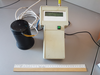
| Figure 1 |
As mentioned above, the main part of the studied instrument is the magnetic noise sensor (Figure 1), which has sufficient sensitivity in the specified frequency ranges. As a sensor of this type, an induction sensor has been selected and manufactured. It consists of a core (layered electrotechnical steel with dimensions of $15 \times 30 \times 90$ mm) and a coil made of 9000 turns of the PEV 0.1-type wire wound over the core frame. Ideally, the sensitivity of such a sensor is directly proportional to the signal frequency, however, the real sensor has the internal capacitance of the coil and the frequency nonlinearity of the core, which is caused by the dependence of the magnetic permeability on the frequency and magnitude of the field. All these factors contribute to the induction sensor's significant nonlinearity in frequency, which must be taken into account during its calibration and in the process of further use.
For building the amplitude-frequency response and linearity verification, the induction sensor was installed in the centre of the single-turn Helmholtz coils of 500 mm by 250 mm, to which a digital generator was connected via a limiting resistor of 50 Ohm. Measurements on the LRC-meter showed that the inductance of the coils with the inserted sensor is 2 $\mu$H, which corresponds to the maximum measurement frequency of 30 kHz to the inductive resistance of 0.4 Ohm (less than one percent of the additional resistance of 50 Ohms). The active resistance of the coils and connecting lines was also negligible (0.1 Ohms), which allowed to exclude it from consideration in the calculation of the current in the coils according to Ohm's law: $I=U/R$. the Magnetic field in the centre of the coils was calculated following the Eq. (1):
\begin{equation} \tag*{(1)} B=\frac{\mu_0 8\: I}{5\sqrt{5}r}=\frac{\mu_0 8 \:U}{5\sqrt{5}rR} \end{equation}where $R$ is the value of additional resistance, $r$ is the ring radius, $U$ is voltage, set on the generator, $\mu_0$ is the magnetic constant.
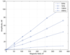 |
| Figure 2 |
 |
| Figure 3 |
When measuring, the generator frequency was set in the range from 10 Hz to 70 kHz with a logarithmic step, while the amplitude of the current in the coils was chosen such that the field was 100 nT. The sensor output amplitude measurements were carried out by means of the digital oscilloscope that was connected to the output of the sensor coil and worked in the signal parameters measurement mode. The sensor's linearity the was examined in 50 nT steps at the control frequencies of 50 Hz, 1 kHz, 10 kHz, and 30 kHz. The measurement results are shown in Figure 2, Figure 3. Based on the dependencies presented in the plots, it follows that the sensitivity of the studied induction sensor for a specific frequency with increasing magnetic field strength varies within 5–10%, while its sensitivity for different frequency ranges has significantly different values.
The sensor's sensitivity for the low-frequency range is very small (less than 0.02 mV/nT), whereas for the high-frequency range it ranges from 0.1 to 0.25 mV/nT, which is an order of magnitude higher than the sensitivity of the sensor at low frequencies. It should also be noted that the sensitivity of the sensor at the 50 Hz frequency is 0.025 mV/nT.
 |
| Figure 4 |
As a rule, the main harmonic of the measured noise lies in the area of the industrial frequency of 50 Hz and its amplitude can exceed the amplitude of the harmonics of the noise in low- and high-frequency bands by several orders of magnitude. This may cause the exceedance of the threshold of the power bus of analogue amplifying filters. The problem that arises in this case can be solved by using the specific scheme, presented in Figure 4.
The signal taken from the sensor is first amplified with a small gain in order to provide a resolution in the 50 Hz channel of the order of 0.1 nT (based on the sensor's sensitivity and the ADC bit width). Then, a narrow-band inverting filter is used to allocate the 50 Hz harmonic. The signal is afterwards fed to an analogue repeater, the output of which is connected to one of the inputs of the ADC that serves as a measuring channel for the frequency of 50 Hz. At the same time, the selected 50 Hz harmonic signal is inverted and summed with the signal taken from the buffer pre-amplifier, using analogue adder. As a result, there is a subtraction of harmonics in the 50 Hz band. Thus, we obtain a rejector filter with an attenuation coefficient up to $-22$ dB that ultimately eliminates the high-amplitude harmonic of the industrial frequency of 50 Hz from the total measured signal.
After the signal is filtered from the 50 Hz harmonic, it is fed to the active amplifying filters of low-frequency (LF, less than 50 Hz) and high-frequency (HF, more than 50 Hz) channels, the outputs of which are connected to separate ADC channels. The filter gain was chosen with respect to the sensitivity of the sensor at different frequency ranges, which, as noted above, differ by an order of magnitude. Accordingly, the gain was chosen as 100 for the low-frequency range and 10 for the high-frequency band. This is done in order to align the resulting amplitude-frequency response of the noise-meter in the low and high frequency bands.
 |
| Figure 5 |
The instrument is managed using a 16-bit microcontroller. The structural-functional scheme of the instrument ("noise-meter") is shown in Figure 5.
Within the experiment the operator selects the point of measurement and presses the start button. The operator should not change his location for approximately 6–7 seconds. Once the start button is pressed, the signal from the induction sensor is recorded. During one measurement experiment 1536 measurements (records) are successively performed: 512 measurements (records) in the high-frequency range within 0.25 seconds with registration frequency of 2 kHz; 512 measurements (records) in the channel for 50 Hz frequency within 1 second with registration frequency of 500 Hz; and 512 records within 5 seconds in the low-frequency range with registration frequency of 100 Hz. Availability of GPS coordinates makes it possible to easily build noise distribution over a large area with a grid interval of 5–10 m (scale $1:5000$ and smaller) according to several measurement experiments.
After the prototype of the developed measuring instrument was manufactured, it was calibrated and tested. This work was carried out at the Baygazan lodge at the Altai State Natural Reserve (Altai Republic, Russia), where the magnetic station of Gorno-Altai State University (GASU) is located. This place is distinguished by the lack of network power supply and other activity associated with the use of powerful electrical equipment, which in turn provides the low level of artificial magnetic noise.
The noise-meter was calibrated at a distance of 1 km from the magnetic station and alternative energy sources using a 1-meter ring and a portable digital generator. An induction sensor was connected to the centre of the ring and connected
to the noise-meter via a coaxial cable 5 meters long. The five-meter distance from the sensor to the noise-meter unit was chosen to eliminate its own magnetic noise, which could be detected by the sensor. It should be noted that the ring was also connected to the generator through a long cable to eliminate the magnetic noise induced by the generator. The magnetic field created by the ring was calculated according to the Eq. (2):
\begin{equation} \tag*{(2)} B=\frac{\mu_0 U}{2Rr} \end{equation}where $R$ is the value of additional resistance, $r$ is the ring radius, $U$ is the voltage set on the generator, $\mu_0$ is the magnetic constant.
 |
| Figure 6 |
This equation is correct if we neglect the capacitance and inductance of the ring, the measurements of which on the LRC meter in the GASU laboratory showed their insignificant effect at the maximum frequencies. The experiment was carried out on a dry wooden table, which also excluded the influence on the measurements of the magnetic field in the ring. The amplitude-frequency response of the noise-meter was obtained with a logarithmic frequency step. The results are shown on plots in Figure 6.
It should be noted that Y-axes of the plots are graduated with the units of counts of the twelve-bit ADC microcontroller with a reference voltage of 3.3 V. As can be seen from the plots, the sensitivity of the low and high-frequency channels remains nonlinear, however at the same time, the maximum values lie in the same range of 250–550 ADC records per nT. The amplitude-frequency response peaks are at 15 Hz and 2 kHz, respectively.
As for the industrial frequency channel, its sensitivity, as it was conceived during the design, is underestimated to 14 units by 1 nT (0.07 nT per ADC-unit), which provided a sufficient dynamic range of 140 nT and a satisfactory resolution of 0.1 nT. At the second stage of the calibration tests, an areal survey of the noise vertical component of the magnetic field at the Baygazan magnetic station was carried out. In these tests, 329 measurement experiments were performed, and thus 329 data-files were obtained. They were subsequently processed in MATLAB in two stages.
 |
| Figure 7 |
At the first stage of the data-files processing, a matrix containing GPS coordinates of measurement points and amplitude values of magnetic noise fields from three channels was created and converted into dBnT, where the value of 1 nT was taken as the reference level. It should be added that while using the Hann digital filter of the 50th order, that the band of the 3rd harmonic of the industrial frequency (150 Hz), which is inherent in all rectifying devices, was identified in the high-frequency channel data. At the second stage of processing, the spatial distribution of magnetic noise field values was obtained using interpolation in dBnT on the polygon map, in accordance with the GPS coordinates (Figure 7).
As can be seen from Figure 7, the main sources of noise are energy converters in the technical pavilion of the observatory, which at the time of the experiment provided power supply to a laptop that controlled the operation of the POS-1 Overhauser magnetometer (usually it is not there). The amplitude of noise in the frequency band of approximately 50 Hz is 2 nT, the amplitude of the multiple harmonic of 150 Hz is 1 nT. The amplitude of noise for the low-frequency channel is recorded at the rate of approximately 0.1 nT. Considerable magnetic noise was recorded near the lodge inspector's house, where the solar panels and the inverter are installed (2 nT at 50 Hz). Among other sources of noise were the proton magnetometer (about 0.1 nT at 50 Hz) and Overhauser magnetometers (up to 1 nT). It is worth to mention, that when analyzing the data on the plot of the 50 Hz range, a noise trace with an amplitude of up to 0.8 nT was distinguished. Its cause was an underground cable with an alternating voltage of 220 V and supply current of about 0.5 A. The measurements were also taken in the vicinity of power generating devices (solar panels and a wind generator), current-carrying cables, as well as converter equipment (inverter), in order to identify their influence over distance. It was revealed that the wind generator (about 15 m in diameter) is characterized by the largest zone of noticeable noise, and the current-carrying cable (about 8 m in diameter) with a similar amplitude of interference (1–2 nT at maximum) has the smallest one. In general, the information obtained during the field testing of the noise-meter described in this work made it possible to select the installation location of a highly-sensitive induction magnetometer [Uchaikin et al., 2015].
The results of laboratory and field experiments show that the portable magnetic noise-meter (Figure 1) described in this paper, due to its circuit design and software solutions used in the development, has the following main features:
The three-channel data representation implemented in this device allows improving the quality of noise analysis by acquiring the ability to measure the multiple harmonics and low-frequency noise resulting from magnetic disturbances induced by passing vehicles and other artificial interference.
Measurements repeatedly carried out using the developed noise-meter made it possible to develop comprehensive technical solutions that minimize the magnetic noise in the measurement pavilions at Baygazan station. This resulted in good recording sensitivity without using digital signal processing, which allowed to observe low-amplitude magnetic variations of the Earth's magnetic field [Gvozdarev et al., 2017].
The developed noise-meter could become a standard solution for assessment of the artificial noise level at geomagnetic stations and observatories. Elimination of the possible sources of artificial noise is essential for producing the high-accuracy geomagnetic data at operational and developing observatories in Russia and neighbouring countries (e.g., "Saint-Petersburg" (SPG), "Klimovskaya" (KLI), "White Sea" (WSE), "Gyulagarak" (Republic of Armenia), etc. [Gvishiani et al., 2018, 2019; Sidorov et al., 2017; Soloviev et al., 2016]).
The noise-meter can be improved by using three component induction sensor to detect horizontal disturbances.
Gvishiani, A. D., A. A. Soloviev, R. V. Sidorov, et al. (2018) , Successes of the organization of geomagnetic monitoring in Russia and the near abroad, Vestnik Otdelenia Nauk o Zemle RAN, 10, no. 4, p. 1–24, https://doi.org/10.2205/2018nz000357.
Gvishiani, A. D., V. I. Kaftan, R. I. Krasnoperov, et al. (2019) , Geoinformatics and Systems Analysis in Geophysics and Geodynamics, Izvestiya, Physics of the Solid Earth, 55, no. 1, p. 33–49, https://doi.org/10.1134/S1069351319010038.
Gvozdarev, A.Y., S. A. Kolesnik, S. Kelyuev, et al. (2017) , Joint research of extremely low frequency electromagnetic background at Baygazan (Russian Altay) and Kolarovo (Tomsk region), 23rd International Symposium on Atmospheric and Ocean Optics: Atmospheric Physics, O. A. Romanovskii (Ed.), SPIE, Irkutsk, https://doi.org/10.1117/12.2286877.
Hrvoic, I., L. R. Newitt (2011) , Instruments and Methodologies for Measurement of the Earth's Magnetic Field, Geomagnetic Observations and Models, M. Mandea, and M. Korte (Eds.), p. 105–126, Springer, Netherlands, Dordrecht, https://doi.org/10.1007/978-90-481-9858-0_5.
Jankowski, J., C. Sucksdorff (1996) , Guide for Magnetic Measurements and Observatory Practice, 235 pp., International Association of Geomagnetism and Aeronomy, Warsaw, Poland.
Khomutov, S. Y., O. V. Mandrikova, E. A. Budilova, et al. (2017) , Noise in raw data from magnetic observatories, Geoscientific Instrumentation, Methods and Data Systems, 6, no. 2, p. 329–343, https://doi.org/10.5194/gi-6-329-2017.
Korepanov, V., R. Berkman, L. Rakhlin, et al. (2001) , Advanced\hfil field magnetometers comparative study, Measurement, 29, no. 2, p. 137–146, https://doi.org/10.1016/S0263-2241(00)00034-8.
Linthe, H.-J., J. Reda, A. Isac, et al. (2012) , Observatory Data quality Control – the instrument to ensure valuable research, Proceedings of the XVth IAGA Workshop on Geomagnetic Observatory Instruments and Data Processing, p. 173–177, Observatory of the Spanish Navy, Cadiz, Spain.
Love, J. J., A. Chulliat (2013) , An International Network of Magnetic Observatories, Eos, Transactions American Geophysical Union, 94, no. 42, p. 373–374, https://doi.org/10.1002/2013EO420001.
Ptitsyna, N. G., G. Villoresi, L. I. Dorman, et al. (1998) , Natural and man-made low-frequency magnetic fields as a potential health hazard, Physics-Uspekhi, 41, no. 7, p. 687–709, https://doi.org/10.1070/pu1998v041n07abeh000419.
Reda, J., D. Fouassier, A. Isac, et al. (2011) , Improvements in Geomagnetic Observatory Data Quality, Geomagnetic Observations and Models, M. Mandea and M. Korte (Eds.), p. 127–148, Springer Netherlands, https://doi.org/10.1007/978-90-481-9858-0_6.
Santarelli, L., P. Palangio, M. De Laurentis (2014) , Electromagnetic background noise at L'Aquila Geomagnetic Observatory, Annals of Geophysics, 57, no. 2, p. 211, https://doi.org/10.4401/ag-6299.
Sidorov, R., A. Soloviev, R. Krasnoperov, et al. (2017) , Saint Petersburg magnetic observatory: from Voeikovo subdivision to INTERMAGNET certification, Geoscientific Instrumentation, Methods and Data Systems, 6, no. 2, p. 473–485, https://doi.org/10.5194/gi-6-473-2017.
Soloviev, A. A., R. V. Sidorov, R. I. Krasnoperov, et al. (2016) , Klimovskaya: A new geomagnetic observatory, Geomagnetism and Aeronomy, 56, no. 3, p. 342–354, https://doi.org/10.1134/S0016793216030154.
St-Louis, B. J., E. A. Sauter, D. F. Trigg, et al. (2012) , INTERMAGNET Technical Reference Manual, INTERMAGNET, Edinburgh.
Stutzke, N., S. Russek, D. Pappas, et al. (2005) , Low-frequency noise measurements on commercial magnetoresistive magnetic field sensors, Journal of Applied Physics, 97, https://doi.org/10.1063/1.1861375.
Szarka, L. (1988) , Geophysical aspects of man-made electromagnetic noise in the earth – A review, Surveys in Geophysics, 9, no. 3, p. 287–318, https://doi.org/10.1007/BF01901627.
Tashiro, K. (2017) , High Sensitivity Magnetometers, Induction Coil Magnetometers, Asaf Grosz and Haji-Sheikh (Eds.), p. 1–39, Springer International Publishing, Cham, https://doi.org/10.1007/978-3-319-34070-8_1.
Turbitt, C., O. Baillie, D. Kerridge, et al. (2011) , An Investigation into Techniques for Isolating Noise in Observatory Data, Data Science Journal, 10, p. 174–182, https://doi.org/10.2481/dsj.iaga-25.
Uchaikin, E. O., D. V. Kudin, A. Y. Gvozdarev (2015) , Design of induction coil magnetometer based on INT-1 sensor and results of monitoring of magnetical station "Baygazan", Proceedings of the XIV Conference of young scientists "Interaction of fields and radiation with matter", ISTP SB RAS, Irkutsk (in Russian).
Received 2 March 2020; accepted 15 April 2020; published 4 May 2020.

Citation: Kudin D. V., E. O. Uchaikin, A. Yu. Gvozdarev, N. G. Kudryavtsev, R. I. Krasnoperov, J. Szollosy, L. Hegymegi (2020), Development and testing of a portable ``noise-meter'' for areal magnetic noise survey, Russ. J. Earth Sci., 20, ES3001, doi:10.2205/2020ES000713.
Copyright 2020 by the Geophysical Center RAS.