 1 the
magnetohydrodynamic equations may be written as
1 the
magnetohydrodynamic equations may be written as
A. D. M. Walker
School of Pure and Applied Physics, University of Natal, Durban, South Africa
Recently Walker [1999] has discussed the proper definition of the energy associated with an MHD wave which is propagated in a moving plasma. Such waves are frequently treated as having a negative energy density [Fejer, 1963; McKenzie, 1970, 1972; Mann et al., 1999]. This can lead to difficulties in interpretation when the waves are localized in space. In this paper we present further discussion of the meaning of the wave energy as defined by Walker [1999] and show how it leads to a consistent picture when studying wave energy which is localized in wave packets. This is important when considering MHD Pc3-5 waves at the magnetopause boundary between streaming magnetosheath and approximately stationary magnetosphere, as well as Pc3 waves propagated between the bow shock and magnetopause.
In a magnetohydrodynamic medium with
b 1 the
magnetohydrodynamic equations may be written as
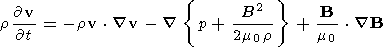 | (1) |
 | (2) |
 | (3) |
 | (4) |
where B is the total magnetic field, r is the mass density, p is the pressure, and v is the plasma velocity.
These are non-linear equations. When dealing with small amplitude waves they are generally linearized by considering the wave perturbation and writing the equations to first order in the small quantities. This is the first stage in a solution by successive approximations. In the discussion which follows we shall need to consider order accuracy. We therefore present below first and second order approximations to the MHD equations.
Assume that
 | (5) |
 | (6) |
 | (7) |
 | (8) |
where the constant uniform equilibrium state is represented by subscript 0, and the first and second order corrections by subscripts 1 and 2. We have allowed for the fact that the plasma may have a drift velocity v0. While it is always possible to consider the problem in the plasma rest frame, our later analysis requires that we allow for this drift velocity.
If these quantities are substituted in equations (1), (2), (3), and (4), and only first order terms are retained, we get the following set of first order equations:
 v1 t = -r0
v0
v1 t = -r0
v0 
 v1
v1
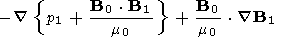 | (9) |
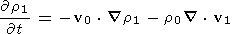 | (10) |
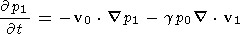 | (11) |
 | (12) |
It should be noted that r1,r2, v1, B1 are exact solutions of these first order differential equations; they are first order approximations to the solutions of (1), (2), (3), and (4).
It can also be seen that the three equations (9), (11), and (12) do not depend on r1. The first order fields are thus entirely determined by solving only these equations. The continuity equation (10) serves only to determine the momentum density once v1, p1, and B1 have been found.
The second order terms in the equations may be written
v2 t+r0
v0
v2+{p2+
B0 B2 m0}
B2 = -r1 v1
t-r0 v1 v1
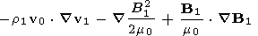 | (13) |
 | (14) |
 | (15) |
B2 t+ v0
B2+ B0 v2-
B0
v2
 | (16) |
If the exact solution of the first order equations, v1,r1,p1, and B1, are substituted in these, then v2,r1,p2, and B2 are exact solutions of these second order equations. Then r0+r1+r2, p0+p1+p2, v0+ v1+ v2, and B0+ B1+ B2 are solutions of the MHD equations (1), (2), (3), and (4), correct to second order accuracy.
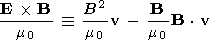
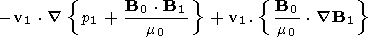
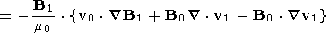
Take the scalar product of v with equation (1), and B/m0 with (4), multiply (2) by (1/2)v2 and (3) by 1/(g -1). If the resulting equations are added, after some manipulation we get
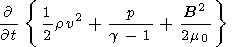 |
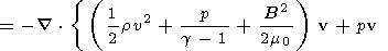 |
 | (17) |
This has the form of an energy equation
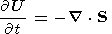 | (18) |
where U is the energy density and S the energy flux.
The three terms of the energy density U represent the kinetic energy density, the thermal energy density, and the magnetic energy density respectively. The terms of the flux have been grouped to give the kinetic energy, thermal and magnetic energy flux, the work done by the pressure force as the plasma moves, and the work done by the Maxwell stresses in the form of magnetic pressure and magnetic field tension. It can easily be verified that the magnetic field terms in the energy flux represent the Poynting vector
 | (19) |
since
 | (20) |
When small amplitude waves exist as a perturbation on a uniform background MHD medium then, to a good approximation, the wave fields can be found from the first order equations (9), (10), (11), and (12). We can then construct an energy conservation equation entirely from the first order wave fields [Walker, 1999]. The result is
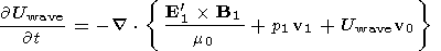 | (21) |
where the first order electric field in the rest frame of the drifting plasma is
 | (22) |
and
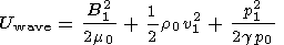 | (23) |
If the Poynting vector is expanded using
 | (24) |
the expression for the energy flux becomes
B1 m0} v1+Uwave
v0
 | (25) |
Each term in (21) involves the product of two first order small quantities. The question arises of how this energy conservation equation is related to the total energy conservation equation (17).
The energy equation (21) is constructed from the first order wave equations. As has been noted, the perturbation quantities v1,r1,p1, and B1 are exact solutions of these equations. The energy conservation equation thus represents the conservation of a quantity constructed entirely from the first order wave solutions. It is clearly not the total energy and cannot straightforwardly be obtained by expanding the energy density obtained from (17) to second order. If one does so one obtains a number of first order energy terms as well as second order terms which are not included in Uwave. To see why this is so let us consider the derivation of (17) in more detail.
The first order equations can be written in matrix form
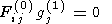 | (26) |
where
Fij(0) is the
8 8 matrix of zero order operators in (9),
(10), (11), and (12),
gj(1)={vx(1),vy(1),vz(1),r1,p1,
B(1)x,B(1)y,Bz(1)}
is a column of the first order
field variables and summation over the repeated suffix is assumed.
8 matrix of zero order operators in (9),
(10), (11), and (12),
gj(1)={vx(1),vy(1),vz(1),r1,p1,
B(1)x,B(1)y,Bz(1)}
is a column of the first order
field variables and summation over the repeated suffix is assumed.
Similarly, the second order equations may be written
 | (27) |
The sum of (26) and (27)
 | (28) |
is an approximation to the field equations correct to second order, and each of the quantities in braces is separately zero.
Let the row matrix fi be given by
 | (29) |
with, zero, first and second order parts fi(0), fi(1), fi(2). Then the process of finding the general energy equation (17), described above, when carried out to second order accuracy, gives
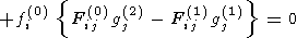 | (30) |
To second order accuracy, this is equivalent to (17). Each quantity in braces is equal to zero. The equation thus shows clearly that, when an equilibrium plasma suffers a small perturbation, the total energy conservation law is the sum of three separate equations, each representing the conservation of a different quantity. The first grouping represents the first order terms in the energy conservation. The last grouping represents equations involving the second order field quantities. The middle grouping may be written
v1 t = -r0 v1 ( v0
v1)
 | (31) |
 | (32) |
 | (33) |
B1 t
 | (34) |
This is not exactly the same as the operation carried out by Walker [1999]. To show how it is related to that process consider (33). Because p is a function of r through the adiabatic relation
 | (35) |
we can express the relationship between p and r through a Taylor expansion which, to second order is
 | (36) |
where
dr r -r0.
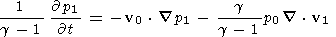
If we differentiate this with respect to t and use (2) we get
 | (37) |
so that
 | (38) |
If this equation is added to (31) and (34), after some manipulation we get the wave energy equation (21). The fourth equation is separately satisfied and does not need to be included, it may be lumped with the other second order terms in (28).
Consider an infinite plane wave varying in time and space as
exp{-iwt+i k r} so that
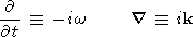 | (39) |
Substitution of these values in the first order wave equations show that nontrivial solutions only occur when the plane waves obey dispersion relations
 | (40) (41) |
where
 | (42) |
and k2=k2x+k2y+k2z. The frequency w0 is that observed in the rest frame of the plasma and w is the Doppler shifted value observed in the frame in which the plasma is moving. The relation D=0 represents the coupled slow and fast waves. The relation F=0 represents the transverse Alfvén wave which, in a uniform medium, is decoupled from the other characteristic waves.
In an anisoptropic medium a wave packet can be constructed as a Fourier synthesis of plane harmonic waves [e.g. Walker, 1993, Chapter 3]. Plane waves move through such a wave packet with the phase velocity
 | (43) |
The wave packet moves with the group velocity
 | (44) |
where
k is the gradient operator
in
k -space. In general the
group and phase velocities have different directions. The ray velocity
VR is defined as the component of the phase velocity in
the
direction of the group velocity. We can also define a velocity
 | (45) |
Note that this is not the group velocity but its component in the direction of the wave normal.
It is useful to normalize the wave vector. The usual way is to define a refractive index vector c k/w where c is the speed of light in free space. For MHD waves this leads to inconveniently large refractive indices. We shall use a "refractive index'' c0 k/w where c0 is some convenient characteristic speed such as the Alfvén speed. An appropriate c0 can be chosen for each problem.
It is convenient to define a number of surfaces which help to define the properties of waves. A more detailed treatment, together with a history of this topic, is given by Walker [1993]. We summarize some of the features here:
- The wave normal surface is a surface in k space traced out by the tip of the vector for possible directions of propagation. It is usually plotted in normalized form as a refractive index surface.
- The direction of the group velocity for a particular direction of k is normal to the refractive index surface at the point where k intersects the surface.
- The ray surface is the surface swept out by the ray velocity. It represents the shape of the wave front emitted by an isotropic source. The phase velocity surface is sometimes erroneously stated to represent the shape of a wave front (see Walker [1993] for a full discussion.)
Figure 3 shows the situation when the plasma drift speed is
greater than
the characteristic speeds of the waves. The format is the same as that
for Figure 2.
Here it is the fast wave which is most dramatically
modified. The plasma drift speed can now exceed the component of the
wave speed for some directions of the wave vector. The consequence is
that the fast wave surface is no longer closed. It is now roughly the
shape of hyperboloids.
Careful study of these and similar surfaces gives insight into the
nature of wave propagation. They are used to determine the direction of
the group velocity, and hence the boundary conditions at infinity in the
negative energy wave picture
[McKenzie, 1970;
Mann et al., 1998]
described below.
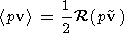
For harmonic waves second order quantities in the energy conservation
equation can be replaced by their values averaged over one period. First
order quantities average to zero. The time average of the product of two
first order quantities, for example
p and v, is given by
where the tilde ~ represents the complex conjugate. The energy
density and energy flux are defined in this sense. In the rest frame of
the drifting plasma, in which
v0=0, the energy conservation
equation (21) becomes
where
w0 is the frequency observed in the
rest frame. In a
frame in which the plasma drifts with a velocity
v0, the
quantity
w0 is the Doppler shifted value of
the frequency
w. It can be shown
[Walker, 1999]
that
where
VG,0=
In the frame of reference in which the plasma is moving, the energy
conservation equation can be written in terms of
w rather than
w0 :
This may be written
Thus, in this frame, the energy density and the energy flux are
An alternative picture of energy flux in moving media involves the
concept of negative energy waves
[Fejer, 1963;
McKenzie, 1970, 1972;
Mann et al., 1998;
Sturrock, 1960].
This
approach has been compared with the approach described above by
Walker [1999].
In this section we compare these two approaches,
amplifying the discussion in that paper.
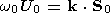
This approach relates to harmonic plane waves. For the negative energy
wave interpretation we follow the treatment of
McKenzie [1970, Appendix I].
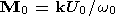
He notes that the Galilean transformation of the energy
density
U and momentum density M are
[Sturrock, 1960]
where the subscript 0 denotes the frame in which the plasma is at rest.
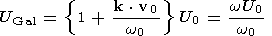
He then takes the momentum density to be the component of the energy
flux in the wave normal direction
k
so that
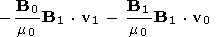
Consider the second term in (49). Previously we considered it to be part
of the energy flux and transposed it to the right hand side where its
interpretation was the divergence of that part of the flux associated
with the transport of wave energy density associated with the plasma
drift. In the negative energy interpretation it is interpreted as part
of the energy density and (56) is used so that
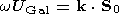
We have seen that the component of energy flux parallel to k in
the rest frame is
w0U0/k. The
energy flux component in the
wave normal direction in the frame in which the plasma moves is the
energy density multiplied by the parallel component of the group
velocity in that frame. If we define
SGal=wUGal/k
then we see that
and
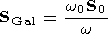
UGal also obeys the wave energy conservation equation:
A consequence of this definition of energy density and flux is that, if
the component of the plasma streaming velocity in the wave normal
direction is greater than the phase speed of the wave then
w0 is negative. In these circumstances
the energy density and energy flux
are negative, leading to the concept of a negative energy wave.
For harmonic waves either approach is possible. For waves which are not
harmonic with a well-defined frequency
w a more detailed
discussion shows that
w0U/w
is more properly the wave
action in the Hamiltonian sense.
Mann et al. [1999]
have shown how energy can be
extracted from streaming magnetosheath plasma in
order to excite waveguide modes in the magnetosphere.
The approach they use is to study the reflection of
waves at the boundary between two uniform media
one of which has a uniform streaming velocity
parallel to the boundary. They follow the approach
of
McKenzie [1970]
using the negative energy wave concept.
Walker [1999]
has discussed the same
problem using the wave energy defined in (21).
Walker [1999]
considers an MHD wave incident on the boundary
between two uniform media. The boundary is in the
x -
z plane, the magnetic field is in the
z direction, and the plasma in the second medium
flows with a uniform velocity V in the
y direction. He defines energy flux according to
(21). He then calculates the energy flux flowing
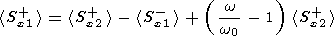
into and out of the boundary, getting the result
The angle brackets denote a time average,
x is normal to the boundary in the direction of
the incident wave, the first and second media
are denoted by subscripts 1 and 2, and propagation
in the positive (negative) direction is denoted by a superscript
+(-). The term on the left hand side is the normal component of
the incident energy flux. The first term on the right is the
transmitted energy flux and the second term on the right is
minus the reflected energy flux so that these two terms together
represent the total flux transmitted away from the boundary. The
last term is zero if the Doppler shifted frequency
w0 is equal to
w, i.e. if
V=0. In this case energy
is conserved at the boundary. Otherwise it represents the difference
between the incident energy and the energy propagated away from the
boundary. Depending on conditions, it may be positive or negative, so
that wave energy may be either lost or gained
in the reflection and transmission process.
McKenzie [1970],
on the other hand, gives expressions for wave
reflection and transmission coefficients which
are equivalent to those of
Walker [1999].
Using (58) as a definition of energy
flux he finds that the ratio of the
energy propagated away from the interface
to the incident energy is always unity,
showing that energy is always conserved
at the interface. In this interpretation
the reflected energy flux can, in appropriate
circumstances, be larger than the incident flux.
Conservation of energy is achieved because the
transmitted wave carries negative energy.
Each of these interpretations gives correct
answers in the context in which it is applied.
The negative energy wave interpretation is
applied in the context of infinite harmonic
plane waves in which the frequency is well defined. Since the energy density
is negative in the second medium, the energy flux vector, which is the
product of the energy density and the group velocity, is in the opposite
direction to the to the group velocity. The boundary conditions for the
second medium require that the group velocity has a normal component
which points away from the boundary. Thus, energy is flowing into the
boundary from the second medium as well as from the first, in which
the source is located. This need not trouble us
in the case of waves which are uniform
in space and time. It is well known that
any definition of an energy flux vector
is not unique; the curl of an arbitrary
vector field of appropriate dimensions
can be added to it without affecting energy conservation
(see, for example,
Panofsky and Phillips [1962]).
Unique results are only obtained when
integration over a closed surface is performed.
Integration over such a surface which lies
entirely in the medium on either side of the
boundary shows that that there is no net flux into or out
of the surface. Only if the surface includes part of the boundary
is there a net flux into or out of it. This implies an energy
source or sink in the boundary and nowhere else. It can be argued
Panofsky and Phillips [1962]
that there is no way to use
the energy flux vector to locate energy flow.
Despite this fact, physicists often feel a sense of
unease with a definition of energy flux which is
inconsistent with the location of known sources of
energy. If it is possible to find a definition of
energy flux which accords with simple minded ideas of
localized energy flow they prefer it. It is worth while
consulting a well-known "elementary'' but sophisticated
source
[Feynman et al., 1964, Chapter 27]
for an enjoyable discussion of this point.
Now consider what the negative energy wave picture
requires us to accept. Suppose that the velocity
V is large enough so that the reflected wave
has a larger amplitude than the incident wave.
It therefore carries more energy than the incident wave.
The negative energy wave picture requires that energy
be conserved in the reflection and transmission process.
The transmitted wave must therefore carry negative energy
away from the boundary. Consider the volume
ABCD. If we
integrate the energy density over this volume at times
t=t1 and
t=t2 the result is zero. Evaluation of the
integral at
t=t3 leads to a negative result. This is
hard to reconcile with the fact that this is the time at
which the wave packet has arrived within the volume. This
is an observable fact. If there were a detector within the
volume it would be excited, presumably extracting energy
from the already negative wave energy reservoir. Another
aspect causing difficulty is the non-locality. At time
t=t2 the total energy at the location of the reflected
wave packet is augmented at the expense of the energy of
the transmitted wave packet which is reduced below zero.
The wave energy picture raises none of these difficulties.
Both transmitted and reflected wave packets carry positive
energy. As described by
Walker [1999],
in these circumstances, both
acquire additional energy at the boundary. The mechanism can be
understood by looking at the details of propagation within the
thin boundary layer. The velocity gradient in the boundary layer
leads to additional Reynolds and Maxwell stresses, which result
in work being done on the wave by the streaming background plasma.
Why does the negative energy picture produce correct results
for harmonic waves but provide puzzling problems when applied
to wave packets which are limited in space and time? First,
we should note that the Galilean transformation should be applied to the
total energy; it is, however, applied to the wave energy in the rest frame.
The expression used is the wave energy in that frame and omits zero and
first order terms. When the Galilean
transformation is applied to find the energy in the frame in which
the plasma is moving, first order terms are introduced. In addition
the period over which time averages are taken is different in the
rest and moving frames. The implication is that some of the energy
associated with the wave in the moving frame is associated with the
background in the wave energy picture. It is possible to resolve the
inconsistencies but only at the cost of elaborate argument. For example,
if the wave is absorbed as described above,
it is necessary to consider not only the negative energy
associated with the flux but also what work is done by
the streaming background plasma at the interface with
the absorber. None of these difficulties arise with the wave energy picture.
It is likely that interaction of waves
with a streaming background plasma is of
considerable importance in understanding
the generation and propagation of MHD waves.
It already appears likely
Mann et al. [1999]
that waveguide modes of Pc5 and longer
period waves can be excited by the counterstreaming
magnetosheath and magnetopause plasmas at the magnetopause.
It is also probable that upstream Pc3 waves are affected by
the magnetosheath flows between the bow shock and the magnetopause
and this may be an important effect in their production. Such a
problem would be best treated by ray tracing in the moving medium.
In such a case wave action is conserved along the ray tubes
but wave energy is not; energy is continually exchanged between
background plasma and wave through the action of the stresses
associated with the velocity gradients. This problem requires
further study. In all such problems it is necessary to have a
proper understanding of the wave energy. There are different methods
of defining energy density which can give correct results if
consistently applied. It is our opinion that the wave energy as
defined here and by
Walker [1999]
is the most satisfying definition, with an intuitively obvious interpretation.
Fejer, J. A.,
Hydromagnetic reflection and refraction at a fluid velocity
discontinuity,
Phys. Fluids, 6, 508,
1963.
Feynman, R. P., R. B. Leighton, and M. Sands,
The Feynman Lectures in Physics, Addison-Wesley, Reading Mass., 1964.
McKenzie, J. F., Hydromagnetic wave interaction with the magnetopause
and the bow shock,
Planet. Space Sci., 18, 1,
1970.
McKenzie, J. F., The reflection and
amplification of acoustic gravity waves
at a density and velocity discontinuity,
J. Geophys. Res., 77, 2915,
1972.
Mann, I. R., A. N. Wright, K. J. Mills, and V. M. Nakariakov,
Excitation of magnetospheric waveguide modes by magnetosheath flows,
J. Geophys. Res., 104, 333,
1999.
Panofsky, W. K. H., and M. Phillips,
Classical electricity and magnetism,
2nd edition, Addison-Wesley, Reading Mass., 1962.
Sturrock, P. A., In what sense do slow waves carry negative energy?
J. App. Phys., 31, 2052,
1960.
Walker, A. D. M.,
Plasma Waves in the Magnetosphere, Springer-Verlag, Berlin, 1993.
Walker, A. D. M., Reflection and transmission
at the boundary between two counterstreaming
plasmas -- Active boundaries or negative energy waves?
J. Plasma Phys., in press, 2000.
 In Figure 1 we illustrate the refractive index surfaces, normalized
in
terms of the Alfvén speed, in a frame
in which the plasma is at
rest. The upper diagram corresponds to
VS
In Figure 1 we illustrate the refractive index surfaces, normalized
in
terms of the Alfvén speed, in a frame
in which the plasma is at
rest. The upper diagram corresponds to
VS
 When the plasma is moving these surfaces are greatly modified.
Figures 2
and 3 show two cases, the first where the plasma drift speed is less
than and the second where it is greater than the characteristic wave
speeds. In each case the magnetic field is in the
z direction and the
drift velocity is in the
y direction. Consider Figure 2. On the left
hand side three-dimensional representations of the refractive index
surfaces for the fast, slow and transverse Alfvén
waves are shown.
On the right hand side three cuts through these surfaces are shown.
These are in the
x-z plane, the
y-z plane, and the
x-y plane through the origin.
The fast wave surface is not affected much. It is still roughly
spheroidal in shape but, because the drift velocity is added to the wave
velocity, it is shifted relative to the origin. The slow and Alfvén
waves are modified more drastically. Although the characteristic speeds
VA,VS, and
(V2A+V2S)1/2
are all greater than the
plasma drift speed, the phase speeds of these waves can be very small
for some directions of the wave vector. This is because the surfaces are
open so that the refractive index approaches infinity for some wave
vector directions. The result is that there is a locus in
k space on
which the component of the phase speed in the direction of the plasma
drift is equal to the drift speed. This locus is a straight line where
the surfaces are singular. The refractive index surfaces for the slow
and Alfvén waves cross on this line. The
ray picture breaks down on
this locus.
When the plasma is moving these surfaces are greatly modified.
Figures 2
and 3 show two cases, the first where the plasma drift speed is less
than and the second where it is greater than the characteristic wave
speeds. In each case the magnetic field is in the
z direction and the
drift velocity is in the
y direction. Consider Figure 2. On the left
hand side three-dimensional representations of the refractive index
surfaces for the fast, slow and transverse Alfvén
waves are shown.
On the right hand side three cuts through these surfaces are shown.
These are in the
x-z plane, the
y-z plane, and the
x-y plane through the origin.
The fast wave surface is not affected much. It is still roughly
spheroidal in shape but, because the drift velocity is added to the wave
velocity, it is shifted relative to the origin. The slow and Alfvén
waves are modified more drastically. Although the characteristic speeds
VA,VS, and
(V2A+V2S)1/2
are all greater than the
plasma drift speed, the phase speeds of these waves can be very small
for some directions of the wave vector. This is because the surfaces are
open so that the refractive index approaches infinity for some wave
vector directions. The result is that there is a locus in
k space on
which the component of the phase speed in the direction of the plasma
drift is equal to the drift speed. This locus is a straight line where
the surfaces are singular. The refractive index surfaces for the slow
and Alfvén waves cross on this line. The
ray picture breaks down on
this locus.
4.3. Energy Conservation for Harmonic Waves
(46) 
(47) 
(48) kw0 is the group velocity.

(49) 
(50) 
(51)
(52)5. Negative Energy Waves
(53)
(54) S divided by the
square of the velocity
VL=dw /dk,
which in the case of MHD
waves is equal to the phase velocity
w /k. The value of
k S is
U0VL. Thus
(55) 
(56) 
(57) 
(58) 
(59) 6. Active Boundaries
(60)  Difficulties with the negative energy wave
interpretation appear when we consider waves
limited in space and time. The definitions (56) and (58)
of energy density and flux only apply when there is a
well-defined frequency. As has already been stated,
the energy density so defined is actually the wave
action. The most general definition of wave action
involves integration over the
generalized coordinates
describing the wave and is beyond the scope of this paper. Any wave variable
can be described by a Fourier synthesis of plane waves. If the Fourier
amplitude is narrowly peaked in frequency and wave number, the wave is
propagated as a well-defined wave packet with a well-determined
frequency and wavelength as illustrated in Figure 4.
This figure shows three epochs in the history of a
wave packet. At
t=t1 the wave packet is travelling
towards the boundary between two media. The lower medium
is at rest and the upper
medium is streaming parallel to the boundary
with a uniform velocity V. The wave packet
moves with the group velocity while wave fronts
move through it with the phase velocity which,
in a dispersive anisotropic medium, does not have
the same direction and magnitude as the phase velocity. These
velocities are schematically shown and are not intended to show
the actual relative directions and magnitudes of an MHD wave.
At time
t=t2 the wave packet has been partially reflected and
partially transmitted at the boundary. At time
t=t3 the
transmitted wave has progressed further and the reflected
wave is no longer within the illustrated region. We emphasize
that this is an observable phenomenon. The wave packet is a
physical disturbance with its own time history.
Difficulties with the negative energy wave
interpretation appear when we consider waves
limited in space and time. The definitions (56) and (58)
of energy density and flux only apply when there is a
well-defined frequency. As has already been stated,
the energy density so defined is actually the wave
action. The most general definition of wave action
involves integration over the
generalized coordinates
describing the wave and is beyond the scope of this paper. Any wave variable
can be described by a Fourier synthesis of plane waves. If the Fourier
amplitude is narrowly peaked in frequency and wave number, the wave is
propagated as a well-defined wave packet with a well-determined
frequency and wavelength as illustrated in Figure 4.
This figure shows three epochs in the history of a
wave packet. At
t=t1 the wave packet is travelling
towards the boundary between two media. The lower medium
is at rest and the upper
medium is streaming parallel to the boundary
with a uniform velocity V. The wave packet
moves with the group velocity while wave fronts
move through it with the phase velocity which,
in a dispersive anisotropic medium, does not have
the same direction and magnitude as the phase velocity. These
velocities are schematically shown and are not intended to show
the actual relative directions and magnitudes of an MHD wave.
At time
t=t2 the wave packet has been partially reflected and
partially transmitted at the boundary. At time
t=t3 the
transmitted wave has progressed further and the reflected
wave is no longer within the illustrated region. We emphasize
that this is an observable phenomenon. The wave packet is a
physical disturbance with its own time history.
7. Discussion and Conclusions
Acknowledgments
This work was performed while the author was in receipt of
funding from the South African National Research Foundation, the Department
of Environment Affairs and Tourism, and the University of Natal Research Fund.
References
Load files for printing and local use.
This document was generated by TeXWeb
(Win32, v.2.0) on August 3, 2000.